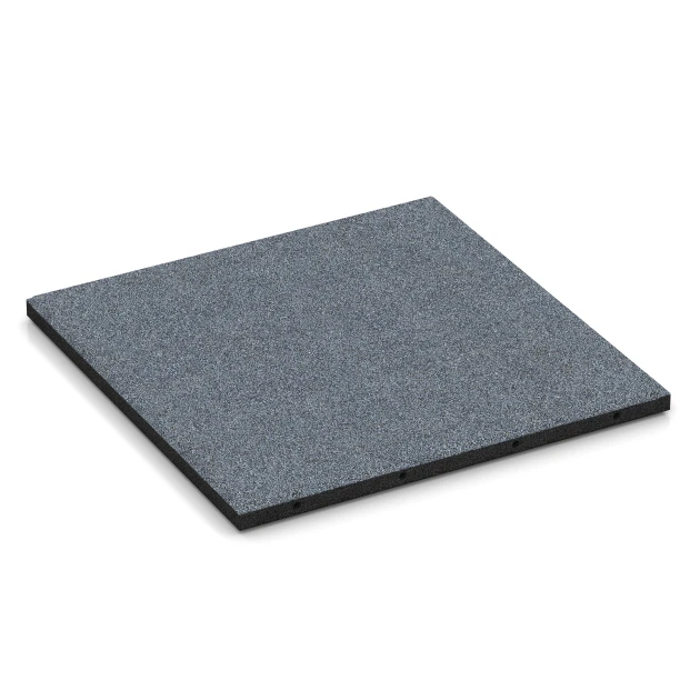
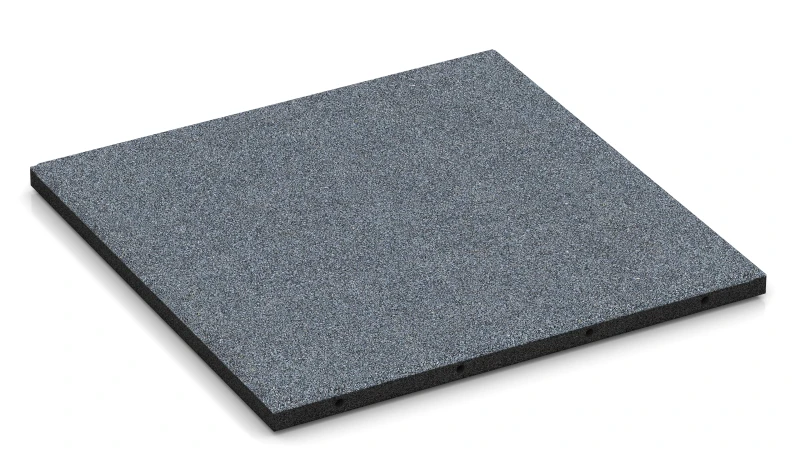
Playground Safety Tiles FP "Graphite grey"
- /
-
Ready to ship
from stock in 1-3 days - £48.00 / 4 Piece / m²
- (5.32 kg / Piece)
EAN: 4251469362901 | Item no.: 6290
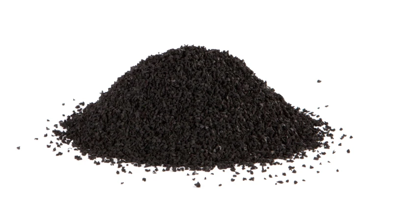
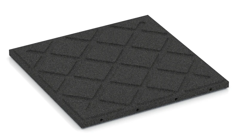
The Type FP playground safety tile cushions the impact when a child falls from a swing, slide or climbing frame in a playground. It is made from rubber granules bonded with polyurethane and is abrasion-resistant and dimensionally stable. The surface is slip-resistant. The edges are bevelled all round, so they slope slightly.
Which thickness is right for each type of play equipment?
Type FP Playground Safety Tiles are available in several thicknesses. The greater the height from which a child can fall off a piece of play equipment, the thicker the tile needs to be. The play equipment manufacturer usually states this height in the product documentation. It is called the free height of fall. For each tile thickness, testing to BS EN 1177 establishes the critical fall height. This is the maximum height from which the tile can still cushion a fall sufficiently. The critical fall height must be at least as high as the free height of fall. A thin tile is therefore sufficient beneath a spring rocker. A thicker tile is required beneath a climbing tower.
How are Playground Safety Tiles laid?
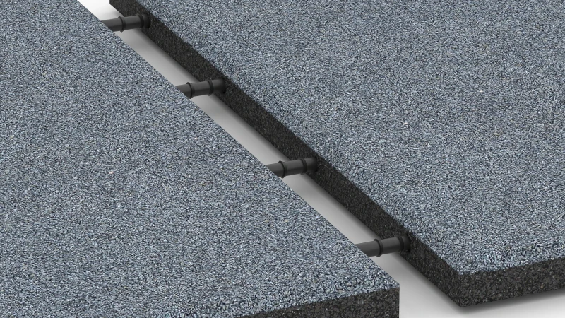
Playground Safety Tiles are laid in a half-bond installation, like bricks in a wall. Each row is offset from the next by half a tile width. The supplied plastic push-fit connectors fit into holes on two opposite edges. They connect each tile to the two adjoining tiles in the neighbouring row. The area should have fixed edging around its perimeter so that the rows do not spread apart in the direction of the connectors. Where the area is installed flush with surrounding grass, paving, concrete or asphalt, no additional edging is usually needed. The tiles are cut with a circular saw or jigsaw.
What base do Playground Safety Tiles need?
Playground Safety Tiles are laid on a firm base such as concrete, asphalt or block paving. On soil, a load-bearing layer of plastic honeycomb grid filled with chippings is required. The honeycomb grid prevents the chippings from gradually moving sideways beneath the tiles. Laying directly on chippings without a honeycomb grid is not recommended. Every base must remain load-bearing and largely level. Rainwater drains through the tiles. On concrete or asphalt, it follows the gradient through drainage channels on the underside of the tiles. On the honeycomb grid, it soaks into the ground.
How much care does the play area need?
Playground Safety Tiles are easy to maintain. Leaves and sand can be swept away with a broom. Stubborn dirt can be removed with a pressure washer. By contrast, a loose-fill playground surface of sand, gravel or wood becomes dirty, is compacted during play and is gradually carried out of the play area. It therefore needs regular cleaning, loosening and topping up.


Discount
Product Highlights
Characteristics
Product Details – Material and Structure
Comparative values
The critical fall height of shock-absorbing playground surfacing is determined by a series of drop tests in accordance with BS EN 1177, not by a critical fall height calculator. A test headform fitted with an accelerometer is dropped from several heights onto points on the surfacing chosen in accordance with the standard. The critical fall height is the lowest drop height at which the impact produces a HIC value of 1000 or a peak acceleration (gmax) of 200 g. The least favourable test point determines the result.
That figure applies only to the surfacing construction tested under the conditions of the test. The test report therefore records the surfacing thickness, the substrate beneath it and the test conditions relevant to the result. On-site testing confirms whether the installed surfacing provides that level of shock absorption: the headform is dropped from a specified height at designated test points, and the readings are checked against the HIC and gmax limits.
The critical fall height is determined to BS EN 1177 in two procedures, one conducted in the laboratory and one carried out on site. The laboratory procedure establishes that value for a surfacing system. The on-site procedure checks at selected locations whether an installed area covers the free fall height of the equipment present. Test specimens with a combined area of at least one square metre are placed on a level, rigid concrete base. Loose-fill surfacing, such as impact-absorbing sand, gravel and woodchips, is installed at its intended depth. Safety tiles are laid so that the joints between tiles are included in the test.
Laboratory impact testing uses a hemispherical 4.6 kg test head, approximately 16 cm in diameter, fitted with an accelerometer, dropped from different heights onto the surfacing. For safety tiles, at least nine drops from at least four heights are made at separate locations 25 cm apart. For loose-fill surfacing, three impacts at each height are made on the same location. Testing is performed at 23 degrees Celsius, with a permitted variation of up to five degrees.
Laboratory results are assessed against the HIC value, which is the head injury criterion, and peak acceleration gmax. The critical fall height is the height at which either HIC 1000 or gmax 200 g is reached, with the lower value governing. It is established by interpolation of the measurement series. The test report gives the critical fall height in metres to two decimal places and states the test laboratory's measurement uncertainty. The result applies only to the tested construction, including tile type, thickness and connection, or, for multilayer systems, the complete layer sequence. The test substrate is the rigid laboratory base, not the site-built construction.
On-site testing verifies whether an installed impact-absorbing playground surfacing covers the free fall height of the equipment present. The test fall height must be at least the free fall height specified for the item of playground equipment under BS EN 1176. Measurements are taken at the least favourable locations, such as areas where the surfacing is worn or where its depth is lowest, and at further representative locations. The number of test locations depends on the size of the impact area, for which the standard specifies a minimum number. This procedure applies only to the locations tested and does not establish a critical fall height.
The thickness of playground safety mats and playground safety tiles must be selected according to their tested critical fall height, which must at least match the free fall height of the playground equipment. The greater the potential fall height, the thicker the mats or tiles need to be.
Thickness alone does not indicate the fall height a product can accommodate. Construction, density and elasticity also affect shock absorption.
As a broad guide for free fall height, the following thicknesses apply: - Up to 100 cm: 3 cm - Up to 150 cm: 5 cm - Up to 200 cm: 7 cm - Up to 300 cm: 10 cm
For shock absorption, the decisive value is always the critical fall height stated for the relevant product in its BS EN 1177 test report.
Playground safety mats and playground safety tiles can be used up to the critical fall height stated in the test report in accordance with BS EN 1177. This is the lowest height at which the HIC value reaches 1000 or the gmax acceleration reaches 200 g. Depending on the product version, the critical fall height is approximately 100 to 300 cm.
up to 100 cm: for example low playhouses, balance equipment
up to 150 cm: for example low climbing elements
up to 200 cm: for example climbing nets, climbing frames, multi-play units
up to 300 cm: for example tall climbing towers and large play structures
These equipment examples are provided for guidance only. The decisive factor is the free fall height of the specific item of playground equipment in accordance with BS EN 1176. The stated critical fall height must be at least equal to that free fall height.
Rubber tiles and mats made from rubber granules typically last 10 to 15 years under normal conditions, and often longer. They are intended for long-term indoor and outdoor use.
Their actual lifespan depends on the intensity of use, the location and weather conditions. On playgrounds, wear occurs mainly in heavily used areas, such as beneath swings and at slide exits. UV radiation and freeze-thaw cycles also contribute to the ageing of rubber granules.
Impact-absorbing surfacing should be inspected regularly for wear and signs of ageing. Where necessary, individual rubber tiles can be replaced without renewing the whole area, which makes maintenance easier and can extend the service life of the overall surface. The surface is easy to maintain.
Playground equipment with a free height of fall above 60 cm requires shock-absorbing surfacing under BS EN 1176. Where equipment involves forced movement, such as swings and slides, surfacing is required throughout the impact area regardless of the free height of fall. For low-level equipment, the requirement depends on both the free height of fall and the type of movement.
The free height of fall is the distance from the clearly intended body support to the impact surface below and must not exceed 3 m. For a platform, the body support is the platform surface; for a swing, the seat surface; and for a horizontal bar, the gripping surface. For climbing, the maximum grip height less 1 m applies. The critical fall height of the surfacing is determined by a series of drop tests to BS EN 1177 and must be at least equal to the equipment’s free height of fall.
Under BS EN 1176, grass and topsoil are acceptable up to a free height of fall of 100 cm, provided the surface is maintained, yielding and free from stones, roots, foundations and other hard objects. Once the ground is compacted, dried out or frozen, these conditions are no longer met. For equipment intended exclusively for domestic use, BS EN 71-8 applies instead of BS EN 1176, and shock-absorbing surfacing is required in a private garden as well.
Playground safety tiles sit more evenly and remain stable for longer on gravel grids than on a loose grit bed. The honeycomb cells hold the aggregate in place, with the material contained within each individual cell. It can neither move sideways under load nor be washed out during heavy rain, so the tiled surface remains stable and safe over the years.
In a loose grit bed, the particles are broadly the same size and lack the fine material that would fill the voids. Even after compaction, the grit remains mobile. This movement is irrelevant beneath a rigid concrete slab, but an elastic playground safety tile or patio tile made from rubber granules does not spread loads evenly through the substrate. Over time, the grit may be pushed towards the tile edges. The rubber tile then loses support in the centre and sinks there, while displaced grit accumulates beneath the edges and lifts them. This pattern of damage is known as dishing.
Gravel grids are also sold as grass grids, gravel cells or plastic honeycomb grids. They turn a loose grit bed into a stable sub-base. When filling the cells, the aggregate is levelled exactly to the top edge. The contained material stays in place under load and in rain, leaving the tiled surface stable and safe. Filled grids can support up to 400 t/m², while the whole area remains water-permeable. Where the ground is permeable, a gradient and drainage are usually unnecessary.
On load-bearing ground subject to low loads, it is sufficient to remove the topsoil and lay the grids on a thin levelling layer of grit. Less excavation is required than for a conventional construction method. A sub-base of compacted crushed stone is only needed where the ground has limited load-bearing capacity, where the construction needs to be frost-proof, or where the area must carry higher loads. This limited amount of work is an argument in favour of gravel grids.
Gravel stabilisation grids can be installed as a sub-base in three ways: directly on in-situ ground, on a grit laying course over the formation, or on a crushed-stone sub-base.
The grid cells are filled with crushed, angular grit. The cells are filled to the top, and the grit is levelled flush with their upper edges.
Where the ground has sufficient bearing capacity and is only lightly loaded, installation directly on in-situ ground is sufficient. Topsoil must first be removed, and the formation must be carefully prepared. The grids are laid directly on the natural ground, allowing the 4 cm ground spikes to penetrate the soil.
A thin grit layer can be laid over the formation to even out irregularities. The ground spikes extend through this grit layer and into the formation.
Where the ground has a low bearing capacity, protection from frost effects is required, or high loads are expected, a crushed-stone sub-base must first be installed and compacted. The ground spikes cannot penetrate the compacted crushed stone. A grit layer is therefore laid over the sub-base so that the spikes are fully embedded. This grit layer must be at least 6 cm thick, and the grids must sit firmly on it.
Gravel grids are also sold as grass grids or plastic cellular grids. The grids are set into the thin grit layer, which is about 2 to 5 cm thick when used to even out irregularities.
Rubber flooring tiles can be installed directly over concrete, screed, asphalt or tiled floors as a loose-laid covering, without an additional sub-base.
With no additional sub-base required, the substrate must still be load-bearing, clean and sufficiently level. Remove loose material, oil and other contamination before laying. Larger irregularities, depressions and changes in level must be levelled out so that the tiles lie stably and do not create obtrusive edges.
The starting point and laying direction depend on the shape of the area and the required pattern. In many cases, starting in the centre helps to align the pattern evenly and produce similar cuts at opposite edges. For other areas, a straight boundary may provide the appropriate starting point.
Lay the tiles according to the chosen layout and join them firmly. Depending on the product, this is done using puzzle joints, dovetail joints or separate connectors. Measure the edge tiles, cut them to fit and then insert them.
Bonding is generally not required. Small cut pieces, stair treads and very small areas may require bonding.
Plastic connectors, also known as connector pins or plastic connecting pins, are cylindrical plastic pins with a profiled surface. They fit into factory drilled holes along the sides of the tiles and connect rubber tiles in adjacent rows. Perpendicular to the connector axis, they prevent the tiles from shifting relative to one another. Along the connector axis, the tiles remain free to move.
The tiles are laid row by row in half bond. The plastic connectors are first inserted into the holes along one side of the tile being positioned. With the connectors leading, this tile is then pressed into the holes in the two adjoining tiles in the row already laid. The connectors are designed to fit tightly, so noticeable force during insertion and when pressing the tiles together is normal. If required, the connectors may be glued in place, which prevents the tiles from drifting apart along the connector axis.
Plastic connecting pins hold rubber tiles and shaped units made from rubber granules in accurate grid alignment. These plastic dowels are a widely used connection method and work in a similar way to wooden dowels, extending several centimetres into each of two neighbouring tiles. In a half-bond installation, each tile connects to two tiles in the preceding row and two in the row behind. Across the pin axis, the pins prevent lateral movement; along the axis, however, the tiles remain movable and can drift apart.
To limit this movement, a tiled area generally requires edge restraint. A level adjoining grass sward can provide this restraint. Alternatively, the plastic connecting pins can be glued in place, or the tiles can be bonded to the substrate. The pins do not resist the natural shrinkage of the tiles, so joints can still open and become wider over time.
Correct installation of safety tiles and safety mats requires the substrate, connection system, fall area, fall height and drainage to be matched to the intended use. This applies to outdoor impact-absorbing surfacing in gardens as well as on public playgrounds. Beneath play equipment, the tested critical fall height of the selected product and build-up must at least match the equipment’s free height of fall. The required dimensions of the fall area depend on the individual item of play equipment.
On concrete or asphalt, safety mats and safety tiles can be installed directly. Rainwater passes through the water-permeable surfacing to the sub-base, from which it is directed by a gradient towards a free edge or an outlet.
On grass or soil, direct installation is not appropriate. A loose fill of sand, chippings or gravel is also unsuitable as a substrate because it shifts over time. Once the turf has been removed, plastic honeycomb panels are laid on a thin bedding layer of chippings and filled with chippings up to their upper edge. The safety mats or safety tiles are then laid over them. Rainwater passes through the complete build-up and can infiltrate into the ground.
For higher loads or unfavourable ground conditions, an appropriately designed sub-base of compacted frost-resistant aggregate is also required beneath the laying course. Further installation depends on the connection system.
For safety mats with puzzle interlocking, the interlocking edge of one mat is pressed from above into the edge of the adjacent mat already in place. This stable connection generally requires neither bonding to the substrate nor edge restraint.
Safety tiles with plug-in connectors are laid in a half-bond pattern. They require edge restraint to prevent lateral movement. On a bound sub-base, bonding may be specified instead of edge restraint, depending on the installation situation.
During installation, safety tiles should have a uniform temperature of no more than about 17 °C and should not be heated by direct sunlight. A rubber mallet helps to position the tiles, while a circular saw assists with cutting. Where the impact-absorbing surfacing ends within a paved area, a securely fixed transition ramp prevents trip hazards.